Are hidden leaks, missing insulation, and overheating equipment quietly draining your commercial facility budget?
Thermal imaging turns invisible surface heat into clear visual evidence, catching expensive structural faults before they trigger emergency repairs. Selecting a dependable thermal camera for building inspection gives property teams instant diagnostic clarity without disruptive demolition.
Here is what verified field science and practical hardware specs say about choosing the right tool.
Key Takeaways
- Subsurface Moisture Mapping: Thermal cameras detect concealed leaks and envelope voids by pinpointing cool regions caused by evaporative cooling and thermal storage differences.
- Non-Invasive Diagnostic Verification: Real-time infrared screening maps hydronic heating loops encased in concrete slabs and catches air loss along active HVAC ducting without destructive wall removal.
- Field-Driven Hardware Matching: Sourcing reliable gear requires aligning detector resolution, visual-thermal blending, temperature spans, and enclosure ratings with everyday contractor duties.
- Clear Model Tiers: The QualiTC family delivers 8 practical handheld choices across multiple performance tiers, including dedicated PC analysis software standard with every single package.
Diagnostic Principles and Field Methodology
Infrared thermography (IRT) is an established non-destructive testing method that evaluates structural envelopes by measuring naturally emitted radiant heat and surface temperature variations. Technical papers prove that thermographic audits allow crews to locate subsurface defects, track building thermal loss, and catch structural deterioration without chipping away building materials.
Academic teams often experiment with airborne drones or 3D point-cloud mapping setups. However, practical field comparisons show that dedicated handheld units offer immediate convenience, direct handling, and quick setup for interior inspections.
Handheld equipment avoids the viewing-angle distortion and glare headaches common to aerial drone passes, and easily outperforms budget smartphone camera clips that lose target clarity over modest distances. In our view, equipping field crews with dedicated handheld hardware remains the most sensible, dependable operational choice.
Subsurface Moisture and Leak Diagnostics
Thermal imagers cannot see through solid wall boards. Instead, they capture surface temperature variations caused by evaporative cooling, thermal mass differences, and moisture accumulation within materials. Expecting an imager to act like an x-ray device invites incorrect conclusions, whereas recognizing surface heat transfer leads to repeatable inspection outcomes.
Take typical American platform wood framing: 2×4 or 2×6 stud bays filled with fiberglass batts and faced with gypsum drywall. When a winter freeze ruptures a pipe or heavy rains breach exterior siding, internal cavities absorb water quickly. Following severe cold snaps or supply line failures, crews must locate damp insulation batts and soaked drywall without tearing down entire rooms.
When detecting moisture behind walls thermal camera devices identify anomalies governed by two thermodynamic principles: evaporative cooling and thermal capacitance.
Moisture migrating through porous building matrices produces latent heat loss via surface evaporation, creating localized cool spots relative to adjacent dry areas. Concurrently, because liquid water possesses a substantially higher specific heat capacity than typical building substrates, damp structural assemblies absorb and release thermal energy much slower than dry areas during natural diurnal or HVAC heating cycles.
Utilizing a dedicated thermal imaging camera for water leak detection allows contractors and inspectors to isolate moisture patterns behind drywall and beneath flooring without invasive tear-outs. However, inspectors must account for physical boundaries and field parameters established in NDT research:
Superficial Depth Limits and Sensor Pairing
Passive surface thermography is primarily sensitive to the top 15 mm of plaster or rendering, and thermal signatures become inconclusive when substrate saturation exceeds critical thresholds in laboratory testing.
Recognizing these depth limits is critical for contractors, which is why research studies often pair infrared cameras with ground-penetrating radar (GPR) to pinpoint deep trapped moisture while thermography maps surface boundary spread.
Diurnal Timing and Solar Avoidance
Field testing on buried piping confirms that nighttime or stable indoor walkthroughs yield far cleaner data than daytime checks, primarily because heavy solar heating, thermal reflections, and confusing shadows distort readings.
Thermal Gradient Thresholds and Anomaly Processing
Tracking fluid movement across civil assets, dams, and pipe networks requires an adequate thermal delta, typically exceeding 5°C between fluid and ambient boundaries, to generate discernible signatures.
In field settings with transient interference, multitemporal tracking, contrast filtering, and shadow modeling isolate true hydraulic leaks from microclimatic noise.
Radiant Heating and Hydronic Circuit Mapping
The thermal manifestation of an embedded pipe depends directly on fluid temperature and the boundary environment. Unlike cold water leaks that produce low-temperature zones, embedded underfloor hydronic heating loops and domestic hot water lines conduct heat upward, creating distinct high-temperature plumes.
In US construction, ranging from concrete slab-on-grade foundations common across the Sunbelt to hydronic retrofits beneath hardwood or tile in Northern states, radiant tubing is encased in concrete or gypsum underlayment. Blind drilling into these assemblies risks puncturing pressurized lines.
Deploying a specialized radiant floor heating thermal camera visualizes active thermal patterns during system warm-up. In our perspective, visual-thermal blending is just as valuable as pure detector sensitivity here, because seeing a warm thermal trace aligned directly with tile grout lines or wall plates provides actionable clarity.
This non-invasive diagnostic workflow allows technicians to perform three vital field tasks:
- Tubing and Cable Mapping: Pinpointing the exact path of active hydronic loops and electric elements before crews drill into slabs or anchor partition framing.
- Hydronic Circuit Balancing: Detecting localized air locks, sediment blockages, and unbalanced manifolds across individual heating zones.
- Concealed Fracture Isolation: Pinpointing subsurface pipe ruptures, which register as diffuse, widening thermal blooms rather than sharp, linear conduits.
Building Envelopes and HVAC Distribution
Thermography provides an established contactless method for assessing building envelopes, mechanical systems, and air distribution integrity. In utility weatherization audits, commercial commissioning, and pre-purchase building surveys, identifying heat transfer anomalies is critical.
Quantitative envelope evaluations demonstrate that localized thermal bridging or missing insulation can reduce the effective thermal resistance of an affected wall section by nearly half compared to an intact assembly.
Thermal audits also detect structural crack air filtration, rendering delamination, and hidden timber framing behind historical finishes without invasive probing. Deploying an infrared camera allows auditors to verify insulation continuity and locate air barrier breaches efficiently.
Similarly, deploying a thermal camera for hvac inspection enables technicians to evaluate forced-air ductwork, packaged rooftop units (RTUs), and compressors during active operation.
In commercial facilities with duct runs in drop-ceiling plenums, air distribution leakage alters conduit surface temperatures as pressurized air escapes through joint ruptures, loose collars, and uninsulated fittings, generating clear thermal anomalies. Recent engineering trials applying computer vision and thermal image streaming have demonstrated reliable localization of duct air apertures ranging from 0.25 mm to 3 mm.
Building envelope air barrier integrity remains closely tied to HVAC operating efficiency. Advanced inspection protocols evaluate these coupled systems using two core approaches:
Pressurization and Blower Door Coupling
When evaluating air barrier integrity under established US frameworks like ASTM E1186 (Standard Practices for Air Leakage Site Detection in Building Envelopes and Air Barrier Systems), thermography is routinely paired with controlled pressure drops. Combining infrared imaging with blower-door fan depressurization at pressure differentials of 25 Pa or greater clearly exposes convective air infiltration paths, shifting localized surface temperatures by roughly 60% of the indoor-to-outdoor temperature differential.
For accelerated screening, transient infrared imaging (TIRI) has demonstrated the capacity to capture door and window air leakage signatures in 10 seconds under short pressure pulses, operating with indoor-outdoor thermal differentials as low as 2 °C.
Automated Anomaly Recognition
Concurrently, academic deep learning frameworks (such as YOLOv7) and computer vision segmentation models continue to validate automated thermal defect classification across building façades and mechanical enclosures.
While automated computer recognition represents an interesting development in academic research, our view remains grounded in field practicalities: regular facility operations still rely on a skilled technician holding a clear, responsive instrument to make real-world decisions.
Core Technical Evaluation Criteria
When sourcing thermal imaging equipment for commercial inspection fleets, engineering teams must evaluate several fundamental operational parameters:
Emissivity Calibration and Sensor Stability
Accurate radiometry depends on setting correct surface emissivity values. Technical assessments demonstrate that incorrect emissivity inputs induce measurement discrepancies of several degrees Celsius, while reflections from adjacent heat sources or solar radiation distort readings.
Furthermore, uncooled microbolometer detectors require an initial preheating stabilization window, typically at least 10 minutes from cold boot, to eliminate internal thermal drift before recording quantitative diagnostic data. In our view, letting a camera stabilize for ten minutes before logging critical data is simple operational discipline that prevents false calls.
Environmental Boundaries Across US Climates
Environmental forces such as wind convection, ambient air shifts, and solar loading can mask subtle surface temperature anomalies.
For example, during commercial rooftop evaluations in the US Sunbelt and Desert Southwest, intense solar loading on flat membrane roofs (such as TPO or EPDM) and outdoor condensing equipment creates severe radiant reflections. Conducting scans during dusk, nocturnal intervals, or early morning avoids solar interference.
Conversely, in cold Northern and Midwestern winter audits, sub-freezing outdoor temperatures make it far easier to satisfy consensus standards like ASTM C1060 (Standard Practice for Thermographic Inspection of Insulation Installations in Envelope Cavities of Frame Buildings). ASTM C1060 recommends maintaining an indoor-outdoor temperature differential of at least 10°C (18°F) for approximately 4 hours prior to and during the survey, while treating thermal anomalies as indicators that require independent physical verification.
Technicians must still account for wind-driven convective surface cooling and solar loading, which can alter surface heat transfer and obscure defect boundaries.
In outdoor envelope studies, maintaining camera viewing angles between 30° and 45° and managing sensor resolution mitigates perspective distortion. In academic research, thermal data is increasingly registered onto digital geometry and photogrammetric models to facilitate long-term retrofit planning.
Analytical Workflows and Data Processing
In advanced testing and academic research, processing thermal data often involves complex algorithms like image segmentation, robust principal component analysis (RPCA), and long-term time-series tracking to filter out background noise. Specialized studies even evaluate non-residential HVAC condensing cycles during nocturnal windows to avoid solar interference or correlate occupant skin temperatures with HVAC settings.
While those advanced analytical methods serve specialized research, daily commercial contracting requires a much more straightforward workflow: capturing field data and quickly turning it into defensible client reports.
From a business standpoint, we believe that basic reporting capability should never be locked behind recurring subscription paywalls. Technicians need to generate clean, professional documentation for property owners and insurance underwriters without paying ongoing software tolls, which is why we provide dedicated PC analysis software standard with every camera package.
Thermal Sensitivity (NETD)
Thermal sensitivity, formally designated as Noise Equivalent Temperature Difference (NETD) and stated in millikelvins (mK), defines the smallest temperature increment a thermal sensor can distinguish from background electronic noise. In thermal imaging, lower mK numbers represent superior sensitivity: a 50 mK detector differentiates surface variations down to 0.05°C, whereas a 70 mK detector resolves variations down to 0.07°C.
For building envelope assessments and sub-surface moisture surveys, where evaporative cooling creates subtle thermal signatures of only one or two degrees, high thermal sensitivity prevents faint moisture perimeters from getting lost in background noise. In our lineup, models like the QualiTC 17 and QualiTC 20 feature 50 mK sensitivity, delivering excellent thermal contrast for indoor drywall leaks and radiant floor lines.
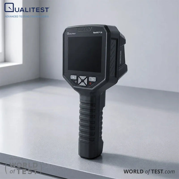
Meanwhile, the QualiTC 25 operates at 70 mK, meeting the standard threshold for commercial building diagnostics while prioritizing higher spatial detector resolution (320×240) across larger facility areas. For heavy industrial diagnostics, our flagship QualiTC 64 provides ≤45 mK sensitivity for resolving subtle heat patterns across broad plant assemblies.
Optical Resolution and Sensor Fusion
Matching detector resolution to actual working distances is simple financial common sense. In our assessment, buyers frequently overspend on high-end pixel counts when inspecting simple, close-range breaker panels where moderate resolution is completely sufficient.
Entry-level sensors handle close mechanical inspections cleanly, but when contractors must scan broad multistory wall assemblies or inspect elevated electrical distribution gear from a distance, higher detector grids (such as 320×240 or 640×480) become essential. Blending thermal images with visible outlines (via outline fusion, overlay fusion, or picture-in-picture) eliminates guesswork by connecting thermal anomalies directly to physical hardware.
Enclosure Durability and Electrical Reliability
Demanding jobsites expose equipment to dust, water spray, and daily wear. Sourcing units with recognized ingress protection ratings (such as IP54) and dependable battery setups (such as 4800 mAh packs or swappable USB-chargeable modules) prevents mid-shift shutdowns in mechanical basements or wet crawlspaces. We consider field durability an essential selection factor that protects maintenance budgets over the long run.
Equipment Selection Matrix
While experimental research often deploys custom robotic crawlers or specialized multi-sensor platforms, commercial facility audits require reliable, self-contained handheld instrumentation. The table below outlines the primary trade focus, infrared detector resolution, and measurement range across our 8 handheld models:
| Model | Primary Trade Focus & Application | IR Resolution | Measurement Range |
|---|---|---|---|
| QualiTC™ 10 | Electrical, HVAC & Mechanical Spot Checks | 120×90 | -20°C to 550°C |
| QualiTC™ 15 | Residential Energy Audits, Plumbing & Water Leaks | 120×90 | -20°C to 550°C |
| QualiTC™ 17 | Plumbing Diagnostics & Distant Target Inspection | 256×192 | -20°C to 550°C |
| QualiTC™ 20 | Mechanical Rooms, Ductwork & Electrical Panels | 256×192 | -20°C to 550°C |
| QualiTC™ 23 | Electrical Maintenance & On-Site Data Sharing | 220×160 | -20°C to 450°C |
| QualiTC™ 25 | Commercial Facility Audits & HVAC Diagnostics | 320×240 | -20°C to 450°C |
| QualiTC™ 38 | Electrical Grid, Utility & High-Heat Industrial Plant Work | 384×288 | -20°C to 1200°C |
| QualiTC™ 64 | Industrial Diagnostics, Petrochemical & Firefighting | 640×480 | -20°C to 1200°C |
Hardware Specifications by Tier
To assist facility managers in selecting the ideal instrument for their operating scope, we organize our cost-effective QualiTC™ models across three functional tiers matched to common US field roles:
Entry-Level Diagnostics and Spot Inspections
Commonly selected by residential home inspectors performing pre-purchase evaluations, service plumbers conducting localized leak assessments, and commercial technicians executing electrical maintenance programs under NFPA 70B (Standard for Electrical Equipment Maintenance), which mandates routine infrared thermography inspections of electrical equipment at intervals not exceeding 12 months:
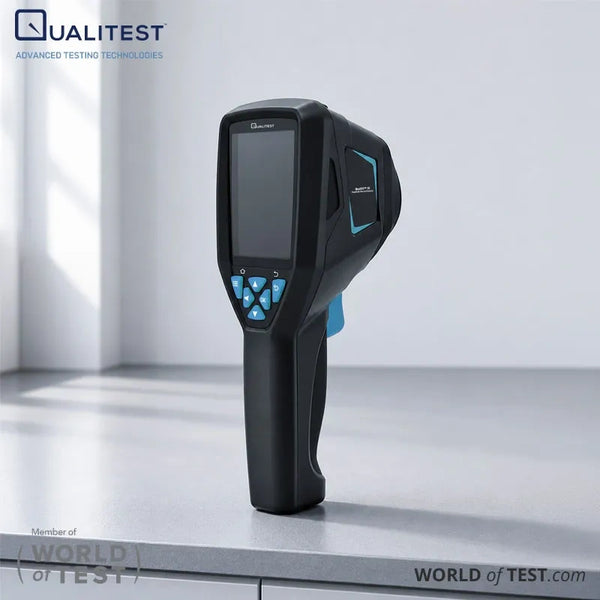
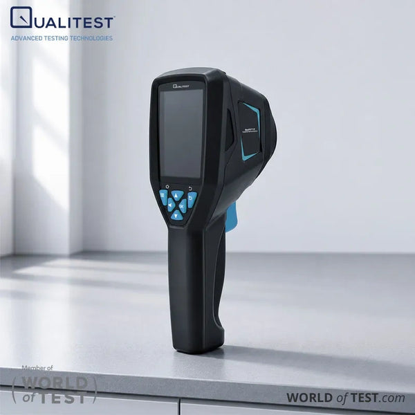
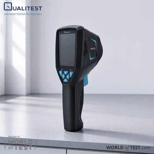
- QualiTC™ 10: Built for routine spot checking across mechanical and electrical equipment, this infrared-only unit provides 120×90 resolution across a -20°C to 550°C measurement range. It includes full-screen hotspot detection, an integrated laser pointer for target verification, and 8GB of internal memory to archive baseline thermal data.
- QualiTC™ 15: Engineered for residential building audits and plumbing assessments, this model pairs a 120×90 thermal detector with a 720P visible light camera over a -20°C to 550°C span. It incorporates outline fusion, overlay fusion, picture-in-picture modes to clearly trace water leak perimeters, alongside an integrated high-temperature alarm for diagnosing active heating pipes and electrical overloads.
Mid-Range Facility and HVAC Systems
Configured for mechanical, electrical, and plumbing (MEP) contractors servicing commercial real estate, corporate office parks, and educational campuses:
- QualiTC™ 17: Increases detector resolution to 256×192 with enhanced 50 mK thermal sensitivity (-20°C to 550°C range) and incorporates visible fusion imaging. It extends onboard distance compensation up to 5 meters, allowing technicians to inspect elevated ceiling runs, ductwork, and floor heating layouts accurately from a distance.
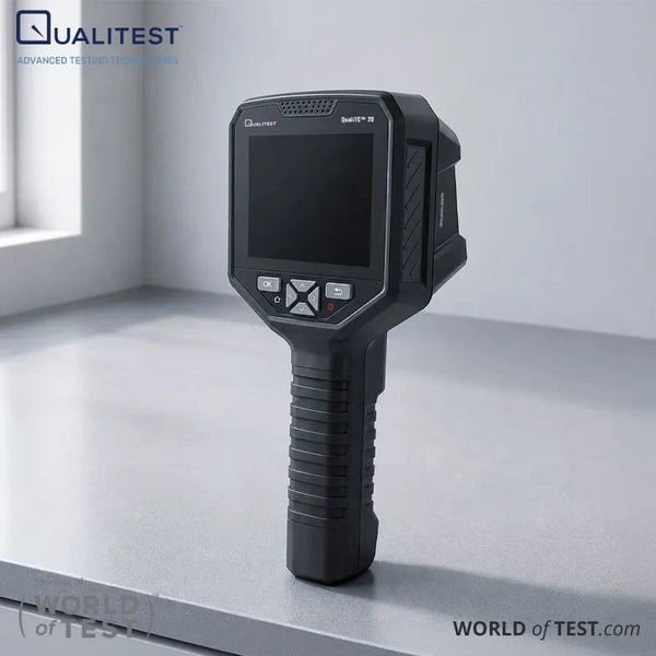
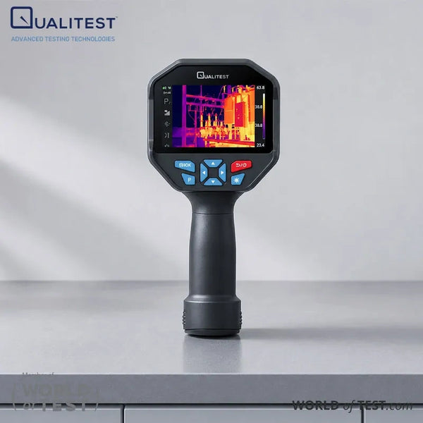
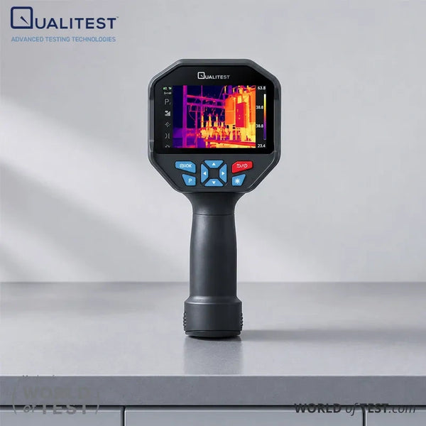
- QualiTC™ 20: Features a 256×192 thermal sensor with 50 mK sensitivity (-20°C to 550°C range) coupled with a built-in 3.5-inch display screen and a wider visible light field of view, providing spatial clarity in crowded mechanical rooms and electrical distribution centers.
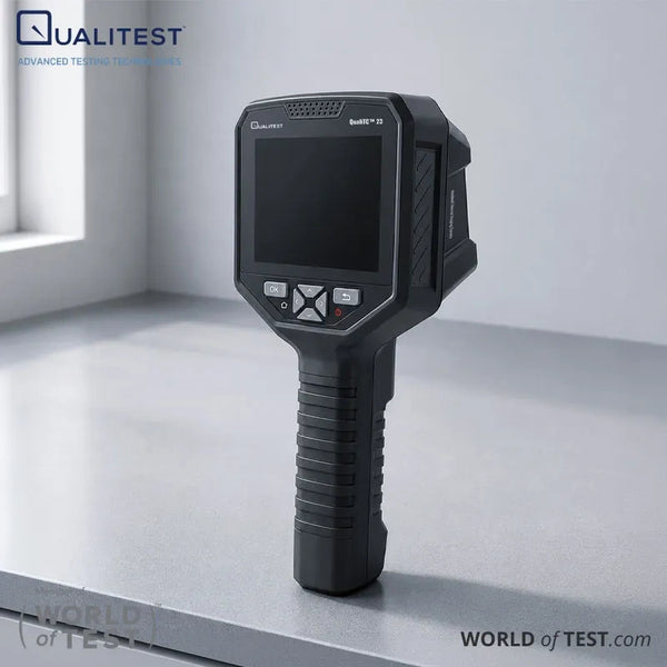
- QualiTC™ 23: Designed for service technicians who need to share data quickly from the field, this 220×160 resolution camera with 70 mK sensitivity (-20°C to 450°C range) features integrated WiFi image transmission and TIFF image export that preserves detailed image data for post-capture analysis.
- QualiTC™ 25: A rugged diagnostic tool delivering 320×240 resolution with 70 mK sensitivity over a -20°C to 450°C range. It features an IP54 ingress protection rating, a built-in 4800 mAh battery rated for approximately four hours of operation, WiFi image transfer, and full-pixel temperature analysis software built for commercial HVAC and electrical distribution maintenance.
High-Temperature Industrial Platforms
Engineered for heavy infrastructure teams, regional electric utility transmission operators, and manufacturing corridors (such as chemical and refining complexes along the US Gulf Coast):
- QualiTC™ 38: Configured for heavy utility and municipal infrastructure, this imager covers temperatures up to 1200°C with a 384×288 detector. It includes a 40-meter laser rangefinder for safe standoff distances, full-frame radiometric video capture, GPS logging, and 4G cellular transmission for immediate field data transfer.
- QualiTC™ 64: Our flagship handheld unit combines a 640×480 thermal sensor featuring ≤45 mK sensitivity with an 8-megapixel (8MP) visible light camera within an IP54 rated housing. Operating across a -20°C to 1200°C measurement range, it includes full-frame radiometric video, laser rangefinding, GPS, 4G connectivity, wireless transfer, and a detachable USB-chargeable battery for continuous industrial diagnostics and firefighting operations.
Equip Your Inspection Fleet With Qualitest
Selecting dependable thermal imaging equipment for building diagnostics, moisture detection, or mechanical maintenance does not require compromising analytical accuracy to meet financial targets.
We believe that by providing clear tier choices and including dedicated PC analysis software standard with every unit, our QualiTC™ series delivers a practical, cost-effective path to dependable thermal diagnostics.
Contact the Qualitest team today to discuss your facility diagnostic requirements, review configuration options with our technical specialists, and request a formal quote.
References (Click to expand)
- Balaras, C., & Argiriou, A. (2002). Infrared thermography for building diagnostics. Energy and Buildings, 34, 171-183.
- Burkinshaw, R. F. (2020). Infrared thermography. How to Investigate Damp.
- Garrido, I., Solla, M., Lagüela-López, S., & García, N. F. (2020). IRT and GPR Techniques for Moisture Detection and Characterisation in Buildings. Sensors (Basel, Switzerland), 20.
- Mahmoodzadeh, M., Gretka, V., Wong, S., Froese, T., & Mukhopadhyaya, P. (2020). Evaluating Patterns of Building Envelope Air Leakage with Infrared Thermography. Energies, 13, 3545.
- Semitela, Â., Silva, J., Girão, A., Verdasca, S., Futre, R., Lau, N., Santos, J., & Completo, A. (2025). Combining Infrared Thermography with Computer Vision Towards Automatic Detection and Localization of Air Leaks. Sensors (Basel, Switzerland), 25.