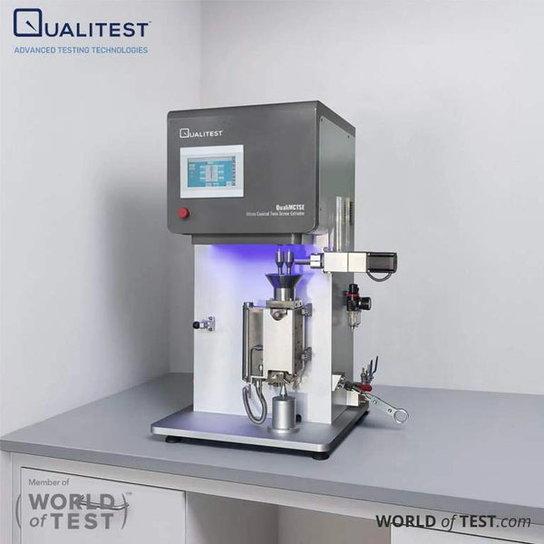
Burning through costly specialty resin just to line out an oversized machine wastes critical R&D capital. Deciding between a conical vs parallel twin screw extruder directly dictates your trial speed and material appetite.
Matching machine volume to scarce sample sizes lets you qualify new formulations in minutes rather than burning through inventory. Here is how both systems compare across mechanics, shear profiles, and benchtop economics.
Technical Specifications Comparison
Across corporate testing centers and academic laboratories, benchtop extruders typically feature screw diameters between 5 mm and 28 mm. Machine dimensions, length-to-diameter ratios, and screw rotation profiles govern shear distribution, fill levels, and material residence times.
In our assessment, matching equipment barrel volume to available sample inventory is one of the most critical decisions a laboratory director can make.
While compact 11 mm to 12 mm micro-parallel extruders can process smaller continuous runs, standard 16 mm to 27 mm laboratory parallel platforms demand substantially larger resin batches. The table below outlines a side-by-side technical evaluation comparing general lab-scale parallel extruders against our QualiMCTSE micro conical compounding system:
| Core Decision Metric | QualiMCTSE Micro Conical Twin Screw (Qualitest) | Conventional Lab-Scale Parallel Twin Screw |
|---|---|---|
| Screw Geometry Profile | Continuous double-helix taper (Large end Φ22.25mm down to Small end Φ8.6mm) | Constant diameter along shaft; modular segmented elements (conveying, kneading, reverse) |
| Minimum Sample Requirement | 5–15g of material per batch | Roughly 20g to 50g on 11–12 mm micro units; 500g to multiple kilograms on 16–27 mm lab lines |
| Batch Capacity & Holdup | 15 ml and 40 ml chambers (circulating feeding documented at 15ml/time on the 15 ml configuration) | Continuous flood or starve feed (typically >100 ml barrel holdup volume) |
| Residence Time Control | Built-in circulation loop with manual bypass valve (independent of barrel length) | Governed strictly by barrel length-to-diameter (L/D) ratio, throughput rate, and screw speed |
| Turnaround & Cleaning Access | 10-minute processing run; barrel opens 180° on hinges for tool-free cleaning of smooth continuous screws | Continuous throughput run; cleaning requires unbolting split barrel halves or pulling segmented screw shafts to clean individual elements |
| Footprint & Installation | 580 x 360 x 780 mm (up to 1000 mm H envelope) / 120kg; benchtop or fume hood mounting | Compact benchtop for 11–12 mm units; extended 1,500 to 2,500 mm bench or floor frames for 16–27 mm lines |
Core Architecture: Conical vs Parallel
The core mechanical divergence between conical and parallel extruders centers on shaft orientation, barrel geometry, and melt conveyance behavior.
Parallel Twin Screw Extruders
Parallel extruders position two shafts side-by-side along parallel centerlines, maintaining an identical screw diameter from the feed throat to the discharge die. Because the cross-sectional area remains uniform throughout the process section, residence time is dictated by the physical length-to-diameter (L/D) ratio, with standard configurations spanning 24:1 to 48:1 or longer.
Polymer moves forward through sequential temperature zones. In co-rotating intermeshing systems, material transfers between screw channels through drag flow to achieve distributive blending.
Counter-rotating parallel machines carry polymer inside closed C-shaped chambers, relying on positive displacement conveying that limits viscous heat generation. Processors install specialized barrel ports along the process length to vent volatile compounds or introduce secondary feeds.
From our perspective, while parallel machinery is exceptionally well suited for steady commercial output, attempting to achieve extended residence times for small exploratory batches inside a long linear barrel introduces a severe drawback: extending the barrel length inevitably expands holdup volume and demands large baseline quantities of raw resin.
Conical Twin Screw Extruders
Conical twin screw extruders feature shafts set on converging axes that taper toward the discharge tip. In commercial production, industrial conical machines (widely used for rigid PVC pipe and profile extrusion) are almost universally counter-rotating, creating alternating high-pressure nip regions that compress and melt low-bulk-density dry blends smoothly.
At the laboratory micro-compounding scale, however, conical instruments are engineered in both co-rotating and counter-rotating configurations, where the broad intake pocket accepts small feed volumes and compresses them into narrower channels without demanding an extended barrel footprint. Rotation direction changes how shear and conveyance interact, making it essential to evaluate specific mixing mechanics rather than assuming all conical platforms rely on identical nip-zone behavior.
In laboratory-scale development, decoupling residence time from physical barrel length offers substantial operational flexibility. Our QualiMCTSE series incorporates an internal circulation loop controlled by a manual bypass valve. Instead of discharging melt immediately, the operator can recirculate the polymer through the screws for extended compounding.
This circulation mechanism supports three standard operating modes:
- Single-Cycle Blending: Rapid single-pass processing for preliminary blend qualification.
- Timed Cycle Blending: Recirculating melt for a programmed duration to achieve targeted mixing and reaction times.
- Continuous Feeding and Blending: Metered, steady-state throughput for ongoing material evaluation.
Screw Geometry: Segmented vs Conical
Conducting a twin screw extruder screw geometry comparison clarifies how differing mechanical profiles apply shear and transfer thermal energy into a polymer matrix.
Segmented Parallel Screw Design
Parallel laboratory extruders rely on splined shafts fitted with modular elements to balance conveying, melting, and mixing tasks:
Conveying Elements
Helical flights featuring right-handed pitch (such as 20, 30, or 40 mm) push solids and molten polymer forward. Forward throughput and pressure generation depend on flight pitch, channel clearances, and rotational speed. Intermeshing self-wiping profiles are determined mathematically by screw radius, centerline distance, and flight count.
Kneading Blocks
Discs arranged at offset stagger angles (such as 30°, 45°, 60°, or 90°) provide dispersive mixing and melt homogenization. Forwarding 45° blocks apply shear while maintaining forward transport, whereas neutral 90° blocks eliminate axial conveying, forcing complete upstream channel fill and creating broad residence time distributions.
Restrictive and Mixing Elements
Left-handed reverse elements convey melt backward against primary flow, generating localized backpressure and elevated shear rates through the collision of rotational shear and reverse pressure flow. Toothed distributive mixers (such as ZME elements) divide and recombine melt streams, improving spatial uniformity with lower viscous dissipation than heavy kneading assemblies.
In experimental configurations, specialized geometries such as variable-pitch flights or pitched-tip kneading discs have been shown to elevate peak shear rates by up to 58% while suppressing unmixed regions.
Modular segmented screws provide unmatched freedom to adjust shear fields, incorporate liquid feed ports, or establish staged devolatilization zones for demanding continuous reactions.
However, for laboratories focused strictly on rapid formulation screening, the mechanical teardown, cleaning, and element reassembly between runs introduce a noticeable turnaround penalty.
Variable-Diameter Conical Screw Design
The flow mechanics within a tapered conical geometry diverge sharply from segmented shafts. Fluid modeling on miniature counter-rotating conical units (such as an experimental system tapering from 23.74 mm to 9.9 mm) indicates that as the screw diameter narrows, circumferential velocity and local shear rate diminish along the axial path toward the die.
This decreasing shear profile prevents localized overheating near the discharge exit while maintaining a narrow, predictable residence time distribution. Numerical simulations demonstrate that while parallel screws distribute material through cross-channel transfer, conical designs generate progressive volumetric compression that provides steady dispersive mixing.
In our QualiMCTSE series, these hydrodynamic principles are translated into an efficient benchtop platform:
- Continuous Taper Profile: Double-helix screws with variable pitch and variable diameter (protected by independent IP) taper smoothly from Large end Φ22.25mm at the intake down to Small end Φ8.6mm at the discharge. While this fixed geometry cannot be reconfigured with modular mixing elements along the shaft, the narrowing flight volume provides smooth, progressive volumetric compression without localized shear spikes.
- Servo Drive & Low-Speed Torque: Driven by a 1.3KW servo motor operating across 1 to 150 rpm, the system is monitored by an integrated torque sensor with a measurement range of 0 to 200 N.m, enabling controlled low-shear processing to safeguard sensitive polymer chains from excessive mechanical stress.
- Wear-Resistant Metallurgy: All screw and barrel surfaces in contact with the polymer are manufactured from wear- and chemical-resistant imported die steel, preserving tight mechanical clearances even when handling abrasive fillers.
Target Material Applications
Equipment geometry directly determines whether a delicate experimental formulation processes cleanly or suffers thermal degradation. Conical extruders have historically served as the benchmark for thermally unstable polymers, particularly rigid PVC pipe and profile blends, because the wide feed port accepts low-bulk-density dry blends easily while the tapered discharge prevents frictional overheating at the die.
Conversely, modular parallel extruders dominate high-output industrial compounding, devolatilization of volatiles, and continuous wet granulation or dry powder blending in pharmaceutical manufacturing.
In experimental biocomposite processing, counter-rotating twin screws deliver localized nip-region shear that effectively disperses solid particulate fillers. However, when processing sensitive biological materials such as proteins or enzymes, studies show that intense mechanical shear within small twin-screw channels can induce molecular unfolding and degradation.
From our perspective, sample conservation and thermal preservation represent the true operational benchmarks during initial formulation development.
Medical & Pharmaceutical Formulations
In biomedical research clusters across Massachusetts, California, and Minnesota, engineering teams frequently develop bioresorbable surgical implants, drug-eluting matrices, and catheter tubing.
Processing biodegradable polymers like PLA, PCL, and bio-copolyesters requires rigorous thermal management to prevent transesterification and loss of molecular weight. The QualiMCTSE provides 6 independent temperature zones held to ±0.5℃, preventing localized thermal spikes.
For pharmaceutical hot-melt extrusion (HME), newly synthesized active pharmaceutical ingredients (APIs) are often available only in small gram-scale quantities during early development.
The QualiMCTSE platform features mixing capacities of 15 ml and 40 ml, with circulating extrusion feeding documented at 15ml/time on the 15 ml configuration, allowing formulation scientists to evaluate solubility enhancement and carrier miscibility without exhausting scarce API inventories.
High-Temperature Thermoplastics
In aerospace and defense programs located in states like Ohio, Texas, and California, structural components, dielectric insulation, and interior parts require high-temperature polymers such as PEEK, PEI, and fluoropolymers.
We believe laboratory compounding hardware must provide substantial thermal headroom to remain viable across advanced engineering polymers. The QualiMCTSE operates up to 350℃ in its standard configuration, with an optional package reaching 500°C.
Nanocomposites & Battery Materials
Across domestic battery research initiatives throughout the Midwest and Southeast (including facilities in Michigan, Ohio, Tennessee, and Georgia), laboratories formulate solid-state battery binders and conductive electrode slurries incorporating carbon nanotubes or graphene nanoplatelets.
Because advanced nanomaterials represent significant expense, conducting trial runs with 5–15g of material allows comprehensive formulation sweeps at a fraction of standard development costs.
Furthermore, research emphasizes that controlling mechanical energy input during compounding is essential to prevent premature fiber attrition and filler breakdown.
Direct Specimen Prototyping
To evaluate tensile properties or surface characteristics without subjecting polymer blends to secondary thermal histories, the QualiMCTSE connects directly with downstream specimen modules:
- Micro Injection Molding Compatibility: Compounded melt transfers immediately into a micro injection molding machine to produce micro-tensile test specimens and small impact test samples directly from the batch without secondary thermal cycles.
- Film Drawing & Spinning Dies: Research teams can pull cast films or produce prototype fibers directly from micro-scale trial batches.
Scale-Up Strategy & Rheological Analysis
Bridging the gap between small benchtop trials and commercial manufacturing lines is a central engineering challenge. Transferring a process to larger machinery involves complex hydrodynamic relationships across differing barrel dimensions.
In our view, micro-scale compounding and large-scale parallel extrusion should be viewed as complementary, integrated phases of an efficient R&D workflow.
Volumetric Scaling vs. Degree of Fill
Studies on parallel extruders show that direct volumetric scaling frequently fails to maintain uniform filler dispersion between laboratory and production equipment. Instead, matching the percentage of channel fill in high-shear kneading zones, known as the percent drag flow method, more accurately preserves distributive and dispersive mixing behavior across different barrel diameters.
In continuous battery slurry production, keeping the specific feed load below 0.01 maintains uniform dispersion whether compounding on 11 mm, 16 mm, or 24 mm screw diameters.
Machine Dependencies & Flow Dynamics
Research in continuous pharmaceutical wet granulation indicates that formulations cannot be directly transferred between differing laboratory extruder models without adjusting screw configurations, as granulate friability and agglomeration behavior diverge significantly across machine designs.
Because shear history, channel fill, and residence time distributions vary between machine types, micro-scale compounding data should be treated as a map of processing boundaries and melt stability limits, rather than a rigid recipe that transfers completely unchanged to a production-scale parallel line.
Economic Drivers and Upstream Screening in US Workflows
In the United States, research teams operating under competitive federal grants (such as SBIR, DOE, or NSF programs) face tight performance milestones where consuming custom-synthesized additives on unsuccessful trials is unsustainable. Similarly, in commercial compounding centers across Ohio, Pennsylvania, and Michigan, toll compounders must balance pilot-line availability against high changeover costs.
Initiating trials directly on a pilot parallel extruder consumes 500g to multiple kilograms of resin simply to stabilize the process. If a newly developed additive unexpectedly crosslinks, degrades, or binds the screws, cleaning and reconfiguring the machine idle a pilot line for hours.
We believe implementing a dedicated micro-screening stage fundamentally protects development capital. The QualiMCTSE structures this process through three practical steps:
- Low-Volume Formulation Sweeps: Requiring only 5–15g of material, complete compounding runs finish in 10 minutes, enabling researchers to evaluate multiple additive concentrations in a single shift.
- Rheological Data Capture: During compounding, our integrated rheological control software records torque curves across 0~200N.m, continuous melt pressure, axial force, and material temperature, while 6 independent temperature zones regulate the barrel to an accuracy of ±0.5℃.
- Informing Pilot Parameters: These data curves map out melt viscosity changes, shear-thinning trends, and processing boundaries. Process engineers can carry these verified parameters directly to pilot-scale parallel machinery without guesswork.
Selecting the Right Extrusion Architecture for Your Lab
When concluding a lab scale twin screw extruder comparison, we believe equipment selection depends on sample availability, cleaning turnaround requirements, and target experimental outputs:
- Select a Parallel Twin Screw Extruder when your experimental protocol demands reconfigurable screw layouts (such as localized high-shear kneading zones or multiple liquid feeds), continuous pilot pelletizing, or direct baseline data collection for 1:1 scale-up to commercial parallel compounding lines.
- Select a Micro Conical Extruder (QualiMCTSE) when the priority is rapid formulation screening, synthesizing costly polymer blends, or gathering rheological property data using small sample quantities (5–15g). The barrel opens 180° for tool-free cleaning, allowing technicians to clean the chamber and change materials in minutes.
In our view, investing in dedicated micro-scale screening capability minimizes resin waste and reduces pilot equipment downtime compared to running undersized trials on production-oriented parallel extruders. At Qualitest, we supply cost-effective products built to help testing laboratories throughout the United States advance their formulation programs efficiently.
If your organization is evaluating equipment or conducting a twin screw extruder screw geometry comparison for upcoming polymer projects, our technical specialists are ready to review your requirements.
Contact Qualitest today to discuss your formulation goals or request detailed specifications for the QualiMCTSE-15 and QualiMCTSE-40 micro compounders.
References (Click to expand)
- Bauer, H., Matić, J., & Khinast, J. (2021). Characteristic parameters and process maps for fully-filled twin-screw extruder elements. Chemical Engineering Science, 230, 116202.
- Chen, J.-N. (2011). Study on the mixing performance of a co-rotating conical twin-screw extruder. Journal of Harbin Engineering University.
- Dryer, B., Fukuda, G., Webb, J., Montemayor, K., Bigio, D., Andersen, P., & Wetzel, M. (2017). Comparison of scale-up methods for dispersive mixing in twin-screw extruders. Polymer Engineering and Science, 57(4), 345-354.
- Lewandowski, A., & Wilczyński, K. (2022). Modeling of Twin Screw Extrusion of Polymeric Materials. Polymers, 14(2), 274.
- Oldemeier, J. P., & Schöppner, V. (2024). Analysis of the Dispersive and Distributive Mixing Effect of Screw Elements on the Co-Rotating Twin-Screw Extruder with Particle Tracking. Polymers, 16(21), 2952.
- Rauwendaal, C. (1981). Analysis and experimental evaluation of twin screw extruders. Polymer Engineering and Science, 21(16), 1092-1100.
- Seifert, S. (2005). Comparison of parallel and conical twin screw extruders from the processing point of view. Plastics, Rubber and Composites, 34(3), 134-142.
- Stasiek, J., & Nieszporek, T. (2002). Problems of Engineering Design and Production of Screws in Counter-Rotating Twin-Screw Extruders. Polimery, 30, 441-449.
- Stritzinger, U., Roland, W., Berger-Weber, G., & Steinbichler, G. (2023). Modeling melt conveying and power consumption of co-rotating twin-screw extruder kneading blocks: Part B. Prediction models. Polymer Engineering & Science.
- Xin, S., Cheng, W.-T., Yang, L., Yin, Y., Chen, S., Zhang, X.-M., & Chen, W. (2022). Hydrodynamics and mixing performance in a continuous miniature conical counter-rotating twin-screw extruder. International Journal of Chemical Reactor Engineering, 20(10), 1117-1130.