Why wait for critical electrical gear to trip and halt production before checking its actual operating health? Hidden resistance points, loose terminations, and unbalanced phase loads generate detectable heat signatures long before total component failure forces an emergency outage.
Equipping your technicians with an appropriate thermal camera for electrical inspection catches degrading hardware early, satisfies insurer mandates, and keeps crews safely outside arc flash hazard perimeters. Here is what facility leaders need to evaluate before choosing their next diagnostic system.
Key Takeaways
- Early Defect Identification: Uncovers localized Joule heating (I-squared-R losses), phase imbalances, and loose connection hardware before unscheduled downtime occurs.
- Regulatory and Safety Verification: Aligns with mandatory annual NFPA 70B inspection cycles, NETA MTS Delta T criteria, NFPA 70E safe approach boundaries, and commercial insurer loss-prevention guidelines.
- Measurement Reliability Factors: Demands accurate surface emissivity adjustments, appropriate electrical load thresholds, and active compensation for outdoor wind and solar loading.
- Scalable Handheld Instrumentation: Our QualiTC handheld options scale from 120×90 at 60 mK for starter enclosure audits directly up to 640×480 at 45 mK for high-voltage utility diagnostics.
Electrical Failure Modes and Thermal Signatures
Thermal imaging allows technicians to pinpoint internal electrical degradation that remains completely invisible during everyday visual walk-throughs. In energized setups, excess heat stems from predictable physical mechanisms across low-voltage assemblies and high-voltage outdoor infrastructure.
Low-Voltage and Enclosure Defects
Loose screw terminals, corroded contact surfaces, and degraded busbar joints create elevated electrical resistance, generating localized Joule heating (I-squared-R losses) that forces operating temperatures to climb under current load.
In our view, loose electrical terminations represent one of the most deceptive hazards across an industrial facility because they show no visible signs of wear until insulation degrades or terminal failure occurs. In continuous-process environments like Gulf Coast petrochemical facilities, constant mechanical vibration can loosen motor control center (MCC) terminations, producing localized hot spots that demand prompt diagnostic attention.
At the same time, three-phase distribution systems carrying uneven electrical loads force overloaded phase conductors, switch contacts, or breakers to run significantly hotter than adjacent circuits.
As we see it, maintaining balanced phases is not just a best-practice guideline; it is a vital operational safeguard against unexpected breaker trips inside mission-critical data center corridors (such as Northern Virginia, Texas, and Silicon Valley), where battery backup (UPS) systems and distribution boards (PDUs) must deliver continuous, uninterrupted uptime for high-density server racks.
High-Voltage and Grid Degradation
Inside high-voltage utility yards and distribution hubs, infrared cameras spot elevated heat signatures across transformer tanks, deteriorating high-voltage bushings, internal magnetic anomalies, restricted cooling fins, and worn contacts on disconnect switches.
Along overhead utility rights-of-way, thermal diagnostic tools identify degraded splices, corroded bridge clamps, and overheating conductor connections. Sweeping these transmission lines also detects surface leakage currents and environmental contamination on porcelain and composite insulators before a flashover sparks a major grid outage.
From our perspective, regular thermal monitoring of overhead line hardware is an essential operational defense against catastrophic line drops and extended customer outages.
Safety Standards and Regulatory Compliance
Running a compliant electrical thermography program in American commercial buildings and industrial facilities requires adhering to recognized technical benchmarks:
- NFPA 70B (Standard for Electrical Equipment Maintenance): Establishes scheduled infrared thermography surveys as an essential predictive maintenance protocol to confirm distribution equipment integrity.
-
NETA Maintenance Testing Specifications (NETA MTS): Evaluates defect severity through Delta T comparisons to establish repair urgency per ANSI/NETA MTS Table 100.18. This industry standard classifies actionable temperature rise into four distinct severity tiers:
- 1°C to 3°C Delta T between similar loaded components (or 1°C to 10°C over ambient): Possible deficiency; warrants investigation.
- 4°C to 15°C Delta T between similar loaded components (or 11°C to 20°C over ambient): Indicates probable deficiency; repair as time permits.
- 21°C to 40°C over ambient: Monitor continuously until corrective measures can be accomplished.
- Greater than 15°C Delta T between similar loaded components (or greater than 40°C over ambient): Major discrepancy; repair immediately.
- ASTM E1934: Outlines the standard guide for examining electrical and mechanical equipment, detailing clear procedures for listing anomalies, recording operating load levels, and documenting environmental variables.
Worker safety, corporate risk management, and insurance underwriting create distinct operational incentives. NFPA 70E defines safe approach boundaries and personal protective equipment rules, highlighting non-contact diagnostic tools so maintenance staff can evaluate energized components while remaining outside hazardous arc flash zones. In our view, compliance standards and insurer guidelines should never be treated as empty bureaucratic exercises.
While NFPA 70B establishes an enforceable annual inspection baseline for standard electrical distribution equipment, commercial property insurers set their own recommended loss-prevention intervals.
For example, Hartford Steam Boiler (Munich Re) recommends a full electrical system infrared survey at least once every three years, while FM Global Data Sheet 5-20 advises testing every one to three years based on equipment history.
Major property insurers treat documented infrared inspections as verified evidence of condition-based maintenance, supporting underwriting reviews, risk ratings, and loss-prevention credits. Conducting non-contact thermal surveys also directly supports OSHA workplace safety requirements by allowing technicians to assess energized switchgear safely outside restricted approach perimeters.
Critical Inspection and Optical Criteria
Thermal measurement accuracy depends directly on surface physics, optical geometry, and ambient field conditions. In our assessment, providing technicians with thermal imaging hardware without establishing clear diagnostic protocols frequently results in false alarms or overlooked equipment failures.
Surface Emissivity and Loading Thresholds
Standard thermography manuals often assume an emissivity setting near 0.95, which is suitable for matte surfaces, vinyl electrical tape, and standard cable insulation. However, unoxidized bare metals, such as polished copper busbars (sitting near an emissivity of 0.07) or newly installed aluminum terminals (ranging from 0.03 to 0.05), reflect over 90% of background ambient radiation.
Leaving a camera at the default 0.95 setting on these shiny surfaces produces readings that appear artificially cool, which can easily conceal severe internal hot spots. In coastal installations along the Gulf and Atlantic seaboards, airborne salt deposits accelerate terminal oxidation, shifting surface emissivity over time and requiring deliberate camera adjustments.
Field thermographers resolve these low-emissivity reflection errors through three established techniques:
- High-Emissivity Reference Targets: During scheduled, de-energized maintenance outages, technicians apply patches of matte black electrical tape or high-temperature flat paint (emissivity near 0.95) to bare contact points, establishing dependable measurement targets for future energized scans without violating NFPA 70E approach boundaries.
- Indirect Insulation Measurement: On energized equipment where physical surface modification is impossible, inspectors measure the surface temperature of adjacent insulated cable jackets or non-metallic terminal blocks rather than bare metal.
- Comparative Delta T Evaluation: Comparing matching phases fabricated from identical metals under balanced electrical loads allows reflection errors to cancel out, identifying phase-to-phase temperature differentials without requiring absolute calibration on bare metal.
Inspectors must record the exact emissivity setting utilized for each scan, as trending component health against historical baseline surveys is invalid if consecutive inspections use conflicting emissivity values.
Furthermore, reliable thermographic evaluations demand that equipment carries an adequate electrical load, ideally exceeding 40% of nominal design capacity per standard maintenance testing specifications, and remains energized under steady load for at least 15 minutes before scanning to establish thermal equilibrium, as loads near the 20% threshold observed in academic literature risk masking serious connection faults due to minimal Joule heating dissipation.
We believe that training field technicians to verify operational loading and emissivity values is what transforms a basic visual scan into a truly defensible predictive maintenance procedure.
Environmental and Climatic Factors
Inspecting equipment outdoors introduces regional American environmental variables that directly alter thermal readings:
- Solar Loading (Southwest and Desert Regions): In arid areas like Arizona, Texas, and Nevada, intense direct sunlight heats exterior equipment cabinets and pad-mounted transformers. Thermographers must schedule surveys during early morning hours or overcast periods to prevent solar radiation from masking internal defects or generating false hot spots.
- Convective Cooling (Midwest and Great Plains): Across open geography, high wind speeds accelerate convective cooling across overhead conductors and open disconnect switches. This moving air strips away surface heat, meaning even a modest detected temperature rise under breezy conditions can indicate a severe internal connection fault.
In our opinion, recording ambient wind conditions and weather data alongside outdoor thermal captures is an indispensable inspection practice.
Spatial Resolution and Working Distance
In high-voltage environments, measuring small target components (such as overhead bridge clamps or conductor splices) from outside arc flash boundaries requires adequate spatial resolution. Without sufficient detector pixel density, technicians face radiometric dilution, an optical condition where a small target fails to cover enough detector pixels to register an accurate temperature value.
Research also demonstrates that pairing visible-light cameras with infrared detectors provides vital structural orientation, making it simple to correlate thermal hot spots with specific component labels inside densely packed electrical enclosures.
QualiTC™ Series Selection Guide
While technical literature frequently explores experimental research systems, operating facilities require dependable, practical commercial hardware. In our assessment, organizations often overspend on excessively complex hardware for basic panel audits, whereas matching detector resolution directly to required working distance delivers the highest operational return on investment.
Our QualiTC series applies these core thermographic principles across eight handheld models configured for distinct operational tiers:
Routine Audits and Enclosure Checks
Specification Tradeoff: A baseline 120×90 sensor with 60 mK thermal sensitivity and a 38° × 50° field of view provides a cost-effective choice for general enclosure scans where components are large and accessible.
However, when technicians must inspect compact wire terminations or step back to remain outside arc flash perimeter lines, stepping up to a 256×192 detector with 50 mK sensitivity and a wide 56° × 42° field of view delivers sharper thermal contrast and broader cabinet coverage, while built-in 5 meters distance compensation corrects for atmospheric transmission losses across that working distance.
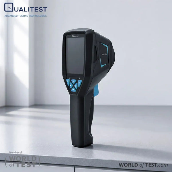
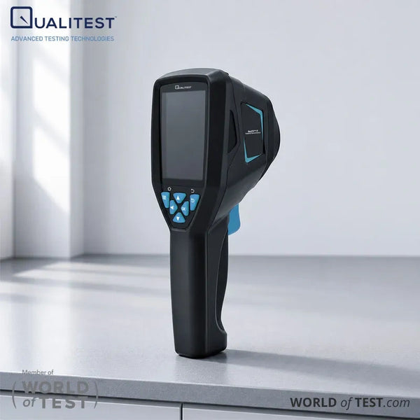
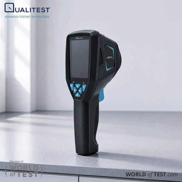
- QualiTC™ 10: Built for everyday electrical, HVAC, and mechanical spot checks, this infrared-only unit delivers a 120×90 IR resolution across a -20°C to 550°C measurement range. It includes a laser pointer, full-screen hotspot detection, and 8GB of internal storage.
- QualiTC™ 15: Pairs a 120×90 IR resolution with a 720P visible light camera across a -20°C to 550°C measurement range. It includes outline fusion, overlay fusion, picture-in-picture visualization, and a high-temperature alarm for rapid defect screening.
- QualiTC™ 17: Increases sensor resolution to 256×192 over a -20°C to 550°C span. It incorporates visible fusion and provides 5 meters distance compensation, making it suitable for smaller targets or deeper enclosure layouts.
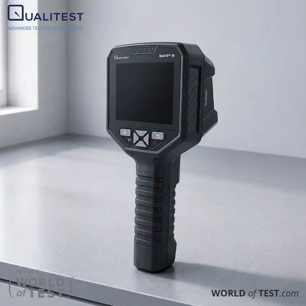
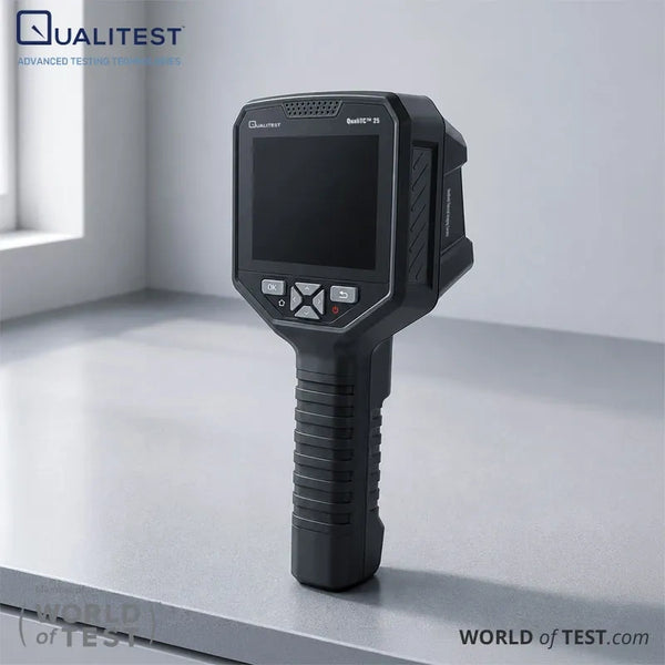
- QualiTC™ 20: Features a 256×192 IR resolution, a -20°C to 550°C range, a visible camera with a wider field of view, and a 3.5-inch display for clear visual assessments during plant audits.
Wireless Diagnostics and Field Maintenance
Specification Tradeoff: This tier represents a lateral shift to workflow efficiency, cable-free reporting, and extended runtime rather than an optical upgrade. Both models in this tier operate with a 70 mK sensitivity floor, which is less sensitive than the 50 mK rating of the QualiTC 17 and 20 in the preceding tier.
Furthermore, the QualiTC 23 drops detector resolution to 220×160 with a 35° × 26° field of view. Choose the QualiTC 23 strictly when wireless TIFF export and rapid image sharing matter more than fine pixel clarity on small contact points.
For teams that require higher resolution alongside cable-free reporting, the QualiTC 25 steps up to 320×240 with a wide 56° × 42° field of view, while adding an IP54 enclosure rating, an extended-life 4800 mAh battery, and dedicated Full-Pixel Temperature Analysis Software for in-depth per-pixel evaluation.
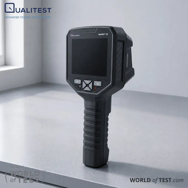
- QualiTC™ 23: Provides a 220×160 IR resolution and a -20°C to 450°C measurement range. Designed for field sharing, it includes WiFi image transmission and direct TIFF image export.
- QualiTC™ 25: Delivers a 320×240 IR resolution across -20°C to 450°C. Built for industrial environments, it features an IP54 rating, an extended-life 4800 mAh battery, WiFi data transfer, and dedicated full-pixel temperature analysis software.
Utility Infrastructure and High-Voltage Lines
Specification Tradeoff: High-voltage switchyards and overhead transmission corridors present long target distances and elevated thermal thresholds. While facility-level imagers cap at 450°C or 550°C, utility and industrial process surveys require thermal measurement ranges extending up to 1200°C and sensitivity ratings at or below 45 mK to resolve subtle temperature differences through outdoor atmosphere.
Stepping up to 384×288 or 640×480 detector grids paired with a 40-meter laser rangefinder allows technicians to pinpoint faint thermal anomalies on overhead line splices and transformer bushings accurately from safe ground positions.
For regional grid operators (such as PJM, MISO, and ERCOT) inspecting substation switchyards before peak summer load seasons, and Western utilities conducting proactive wildfire risk mitigation surveys along forested transmission corridors, these specialized optical instruments are indispensable:
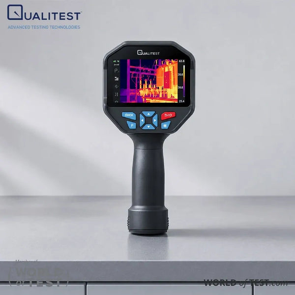
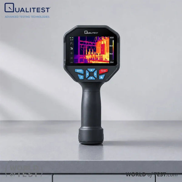
- QualiTC™ 38 (Portable Thermal Camera - Professional): Serving as a capable substation thermal imaging camera, the QualiTC™ 38 provides a 384×288 IR resolution and a broad measurement range from -20°C to 1200°C. It integrates full-frame radiometric video, GPS location logging, 4G cellular transmission, and a 40-meter laser rangefinder to safely verify distances across outdoor switchyards.
- QualiTC™ 64 (Portable Thermal Camera - Advanced): Engineered as a premier power line thermal inspection tool, this flagship unit features a 640×480 IR resolution across a -20°C to 1200°C temperature range. Equipped with an 8-megapixel (8MP) visible camera, radiometric video, GPS logging, an IP54 enclosure rating, and a detachable USB-chargeable battery, it is configured for comprehensive utility and transmission surveys.
Post-Inspection Analysis and Reporting
Collecting thermal data is only the initial step of condition monitoring. In our view, an infrared scan is only as valuable as the corrective maintenance action it produces; without structured post-processing and reporting, critical field findings risk being overlooked.
Technical literature confirms that manual review of large image volumes can be time-consuming and prone to subjective interpretation. Commercial reliability programs depend on systematic offline evaluation to validate corrective work orders.
Every camera in our QualiTC handheld lineup includes dedicated PC analysis software for offline review and formal report generation. Analytical capabilities scale with hardware tiers: the QualiTC 15 and 17 feature 3D thermal analysis software, the QualiTC 25 includes dedicated Full-Pixel Temperature Analysis Software to evaluate temperature values across every pixel in a saved image, and the QualiTC 38 and 64 incorporate full-frame radiometric video analysis.
Technicians across all models can adjust color palettes to emphasize thermal gradients and navigate settings using multi-language interfaces.
Protect Critical Electrical Assets with Qualitest
Balancing compliance requirements, technician safety, and equipment budgets requires dependable diagnostic instruments matched to your operating scope. At Qualitest, we supply practical, cost-effective products backed by technical expertise to keep your electrical systems operating reliably.
Contact Qualitest today to request a quote or consult with our technical specialists to find the right QualiTC thermal camera for your electrical inspection program.
References (Click to expand)
- Balakrishnan, G., Yaw, C. T., Koh, S., Abedin, T., Raj, A., Tiong, S., & Chen, C. (2022). A Review of Infrared Thermography for Condition-Based Monitoring in Electrical Energy: Applications and Recommendations. Energies, 15(16), 6000.
- Huda, A. N. S., & Taib, S. (2013). Application of infrared thermography for predictive/preventive maintenance of thermal defect in electrical equipment. Applied Thermal Engineering, 61, 220-227.
- Minkina, W., & Gryś, S. (2024). Thermographic Measurements in Electrical Power Engineering: Open Discussion on How to Interpret the Results. Applied Sciences, 14(11), 4920.
- Xia, C., Ren, M., Dong, M., Xu, G., Xie, J.-C., & Zhang, C.-X. (2020). Infrared thermography-based diagnostics on power equipment: State-of-the-art. High Voltage, 6, 387-407.
- Zarco-Periñán, P. J., Zarco-Soto, F. J., Zarco-Soto, I. M., & Martínez-Ramos, J. (2022). Conducting Thermographic Inspections in Electrical Substations: A Survey. Applied Sciences, 12(20), 10381.